The handout of the ignition lock of the VAZ-2109 consists of several contacts and the wires summed up to them. The connection scheme is quite simple.
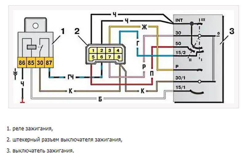
Ignition lock diagram VAZ-2109
Most of the cars and go further helps the device for such an operation – the ignition lock. It is equipped with both foreign -made cars and the products of the domestic automobile industry, in particular, our nine. Damage or malfunctions in the operation of this element will create difficulties for starting the engine by the driver.
Variety of locks for VAZ 2109
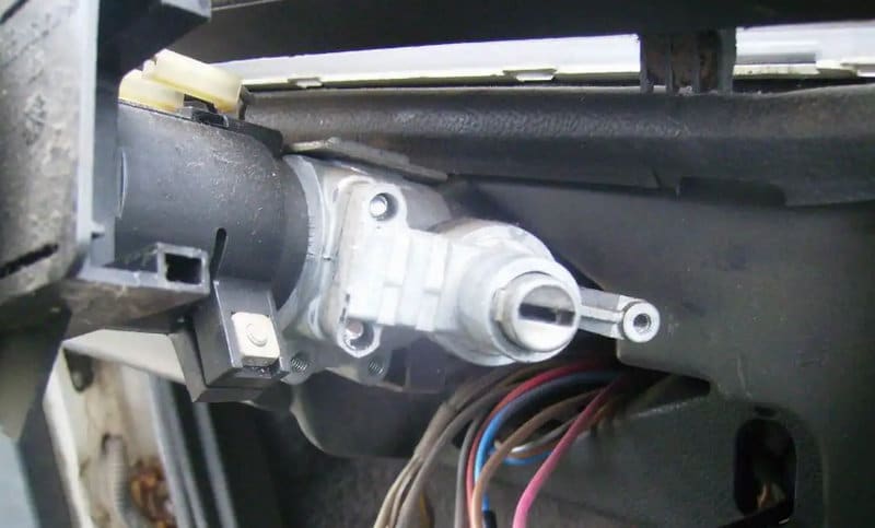
Having abandoned the left -sided location as in the “classic”, the designers took care of a comfortable right place to use the key in their first front -wheel drive cars. This added ergonomics in the cabin. To fulfill its function, the main one used to start the car is equipped with two components:
- mechanical;
- electric.
The first block is responsible for fixing the steering wheel at the time when the key is removed. In the second block, there is a cut of the ignition lock of the VAZ-2109, which is entrusted with a mission to supply voltage to electrical appliances.
The developers have provided for certain electrical appliances in the ninth Lada model, which are able to work regardless of the state of the ignition unit. These include:
- car flashing emergency;
- Feet from the back lights;
- Dimensional optics;
- salon lighting;
- Light bulbs of the instrument panel.
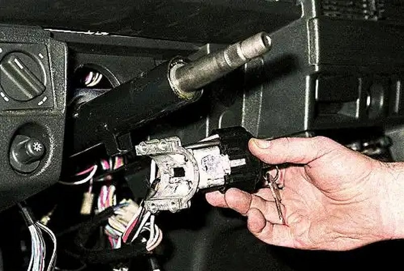
It should be borne in mind that the ignition switching circuit VAZ-2109 is adjusted to its immediate variety. Two types of locks can be installed in nine:
- The late example, in which three provisions are provided, is not used by the relay and activation is carried out by a short key;
- An early example, in which there are four fixed provisions, is built -in relay and a long key is provided.
Typically, drivers easily visually determine the type of installed system. You can navigate the working length of the key.
Used inclusive modes
Each of the thunders provides for the connection of certain devices. Before the nest in a circle there is marking indicating the position that corresponds to a certain regime.
Null
To activate this mode, it is enough to insert the key into the “secret”. In this case, devices that are directly connected to the battery remain active.
Additional consumers will be commissioned after turning the larva to a certain angle. The voltage comes to contacts 30/1 and 30.
The first is ignition
In the first position, the driver is available to the front light, like the near and far lobe lantern. The tidy and the salon are responsibly glowing. The connection of the ignition lock VAZ-2109 is involved in this turn, starting the current for a pair of 30–INT.
When there is a connection of terminals 30/1 and 15/1, then the rear lights, reversing light, turn signals are operational, the excitation winding of the generator is fed. The solenoid valve XX is also energized.
In this position, contacts 30/1 and 15/2 are closed, which ensures the operation, in addition to the head light optics, of the fog lights, the rear window cleaner and its heating. The headlight cleaners, the heater fan and the propeller of the engine cooling system are connected to this contact.
The second is the starter
By moving the key to the current position, the driver does not block the connection of electrical consumers launched at the previous “ignition” position. This fully applies both to the closed contacts of the pair 30/1 – 15/1, and to the pair 30 – INT.
The main change that the VAZ-2109 ignition switch connection diagram gives in such a situation is the actuation of a pair of contacts 30–50. This allows the starter to start.
It is important to know that the key is not held in the “starter” position on its own, but it springs back to the previous position automatically as soon as the driver releases the force.
The third is parking
With this angle of rotation, the consumers that are started in the ignition position, contacts 30 – INT are closed. A closed pair 30/1 – P is also added. It is responsible for parking lighting.
Testing serviceability
The service life of the lock is limited. After its failure, it is necessary to carry out repairs or a complete replacement of the product. The operability is checked after inserting the key into the secret.
Malfunctions occur due to mechanical wear or loss of contact. The check is carried out by turning the key. If it starts to jam, then as a temporary solution, it is possible to use silicone grease by dropping it inside.
In order for the wiring diagram to function correctly, you need to know which contacts to connect to each other. Usually use the following system for wires:
- red connects to the cable from the starter;
- the pink wire goes to + from the 12 V battery;
- brown +12 V is used to start the ignition relay;
- white – relay activation;
- black and blue connect other consumers.
It is necessary to check the contacts for the presence of carbon deposits or for the possibility of oxidation. Burning contacts can be heard in the cabin by the characteristic smell of burnt insulation.